
Smarts Aluminium Fitters Guide
Smarts aluminium fitters instructions: Guide to Installation, Maintenance & Repair
Section 1
Section 2
Cleaning, Maintenance & Repair
Site Survey
Good surveying is the basis of ensuring a quality installation. Surveyors should be fully trained in window and doorset installation techniques, and in the manufacturer’s recommendations for the particular system being used.
- Establish the Customers requirements?
- Asses the aperture for suitability†
- Measuring the aperture
- Calculating the manufacturing sizes
- Performance and Special Requirements
- Structural loading requirements†
- Installation techniques
Establish The Customer’s Requirements
The surveyor should confirm with the purchaser whether the window or door is to be inward or outward opening and the handing and any special specification requirements. The survey is responsible to advise of hardware options and establish the purchasers requirements. In order to demonstrate compliance with Building Regulations (see Note 3), it is advisable to record the style of the window or doorset being replaced along with the size of any opening lights and the positions of any mullions and transoms. Ideally, this would be with the use of photographs and witnessed by the purchaser and countersigned.
The surveyor should inform the purchaser of any enhancements that could be made with respect to any apparent security issues. On outward opening doors, it is strongly recommended that a restriction device, e.g. a door stop positioned as close to the opening stile as possible, is fitted to help avoid damage caused by sudden wind gusts. The protrusion of outward opening windows into the path of pedestrians should be taken into account.

Asses the aperture for suitability?
The surveyor should check for any apparent defects and deficiencies around the structural opening. If any defects are found, then the purchaser should be notified, and agreement reached as to who is responsible for rectifying these defects prior to the new windows or doorsets being installed. For large replacement contracts, it can be advisable to remove one window or doorset to check the condition of the reveals and existing DPM, in so far as this is possible.
Additional Services?
Brickwork Removal?
The presence of any electrical or specialist items such as television aerials and telephone wires in the aperture should be noted. Wherever possible such services should be routed around, and not through, the outer frame of the window or doorset. When this is not possible, a solution should be agreed with the purchaser which does not compromise the performance of the product.
The presence of any curtain tracks in the aperture should be noted. This is particularly important for inward opening or pivoting windows and net curtains. These could either cause problems during installation, or interfere with the function of the window or doorset after installation. Action to prevent any problems should be agreed with the purchaser prior to the installation.
Where bricks are to be removed to install products, the method of any cavity closing should be specified. The method of making good should be agreed with the purchaser. It is advisable to consult local authority building control to ensure that any local interpretations, for instance with respect to cavity closing, are taken into account.
Measuring the aperture
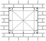
Generally three measurements of width and height should be taken and the squareness of the aperture determined by, for example, taking diagonal measurements (see Figure 1). The smallest measurement of width and of height is used to determine manufacturing sizes.
Sub Sill Required?
Checked Reveals?
Generally three measurements of width and height should be taken and the squareness of the aperture determined by, for example, taking diagonal measurements (see Figure 1). The smallest measurement of width and of height is used to determine manufacturing sizes.
The need for any sub-sill should be determined. The size of the sub-sill should be such that there is an overhang of at least 25 mm from the face of the building. The surveyor should determine how the sub-sill is to be fitted, taking into account features such as horns, and how any making good is to be carried out. The difference between internal and external reveal sizes should be determined and checks made to ensure that the operation of any opening light will not be impeded by plaster, render or tiles, etc. A window or doorset with a check reveal it is a good idea to remove an internal architrave from the window or doorset, to be see exactly how deep the reverse brick detail really is and to identify how much of the outer frame can be put behind in the width. A hole should be drilled through the head of the existing box frame to ascertain the maximum height the window or doorset can be put behind the brick. Quite often this differs greatly from the width. Once the amount of rebate is determined, the window/door height and width should be calculated, taking into account the deductions from Table 1 (see 5.15). If the rebate is sufficient, a 12 mm minimum overlap per side should be allowed. A deeper outer frame might be needed to allow opening out lights to adequately clear the masonry.
Calculating the manufacturing sizes
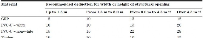
With some framing materials, significant expansion and contraction is to be expected due to temperature fluctuations, and this should be taken into consideration. Allowances should also be made with regard to the window or doorset and building aperture tolerances. When calculating height deductions, due allowance should be also made for the thickness of any silicone or mortar bed at the sub-sill.
Surveying for New Build
The manufacturing sizes and details of installation in new build are normally decided by the house designer in conjunction with the window and doorset supplier in accordance with current Building Regulations. The surveyor should ensure that the details agreed are suitable for the products to be used and are clearly defined.
NOTE The use of proprietary cavity closers/sub-frame systems can enable accurate construction of the opening and simple installation of the window and doorsets. Given the abuse that doors are often subjected to,
caution should be exercised in adopting this method for the installation of doorsets. If in doubt, advice should be sought from the system supplier/manufacturer. It should be brought to the house builder’s attention that factory- finished windows and doorsets need to be programmed for installation as late as possible in the building process to minimize the risk of damage.
Performance and Special Reqnirements
Performance and special requirements should always be considered, such as:
Weathertightness
The surveyor should determine the design wind load for the application, and then determine whether the windows and doorsets are suitable for that exposure. BS 6375-1 gives guidance on selection and specification of windows and doorsets. Where any doubts exist, the manufacturer should be consulted.
Drainage Thresholds
Letterplates
Hardware Side Panels
Georgian Bars
The surveyor should specify or confirm any method of drainage of frame and/or glazing to be used. Consideration should be given to the type of threshold and any protection for it that will be required. The size and location of any letterplate should be confirmed with the purchaser; Any requirements for additional hardware such as trickle vents, cat flaps, spy holes, etc., should be clearly specified. On doorsets with side panels, it might be necessary to take mullion bounce into account and stiffen the mullion to limit this. Any such stiffening should be clearly specified. The surveyor should specify or confirm the position, style and orientation of any glass pattern or decoration, including leading or Georgian Bar inserts, and the need for any alignment.
Planning Permission Attention is drawn to the legal requirement to identify the need for any planning permission, e.g. for listed buildings or in conservation areas.
Risk Assessment A risk assessment should be carried out for the suitability of the window or doorset design. The responsibility for this lies with the designer of the window or doorset, and it should be carried out by a competent person (commonly the surveyor). Suitable written records should be retained.
Cleaning Requirements Information on the safety of windows (including door-height windows) in use and during cleaning is given in BS 8213-1. In the case of domestic replacement windows and doorsets, the designer is the person or organization taking the order from the purchaser.
Structural loading requirements?
When a load-bearing situation is suspected or confirmed then it is essential that the system supplier’s recommendations are followed.
Bow Windows? Where bow, oriel or dormer windows have applied loads, special structural calculations may be necessary. Where any doubts exist, the structure should be assumed to be load-bearing and reference made to the system supplier’s instructions.
Coupled Windows? Where windows and/or doorsets are to be coupled, the surveyor should determine the method to be used, taking into account wind and dead loads, visual appearance and position of the coupling.
Window/Door Lintel? The surveyor should take reasonable steps to check that there is a lintel or other means of supporting the structure above the window or doorset. Where no such support exists and the load is carried on the existing window or doorset, then alternative means of providing this support should be provided.
Installation techniques
Wherever possible the survey should identify any necessary variations to standard installation techniques such as lug fixing or direct fixing.
Removing existing products
The installation team should ensure that all relevant documentation, e.g. drawings, survey sheets, special instructions, etc., is available and understood, and that the relevant products and equipment are available. Prior to the commencement of work the sizes, type, and condition of all windows and doorsets should be checked both against the survey sizes and types and against the actual aperture sizes.
The installer is responsible for both internal and external protection of the property during the installation work. The existing windows and doorsets should be removed with care to avoid unnecessary damage to the building structure and its finishings, and without permitting any subsidence of the superstructure during or after the installation procedure. Care should be taken to avoid debris becoming embedded in soft garden areas (lawns, etc.). Care should be taken to avoid soiling of or damage to floor coverings and to decorations. Damage will inevitably be caused to the reveals adjacent to the installation, and it is essential that reasonable care be taken to keep this to a minimum. At the request of the installer, prior to the commencement of work, the purchaser should be given adequate notice to remove any furniture, fixings or fittings that might otherwise be damaged during the installation.
The installer should plan to install and seal the new windows and doorsets on the same day that the existing windows or doorsets are removed, to maintain security and the weathertightness of the structure. When this is not practicable, for example on large contracts, an alternative arrangement for security and weathertightness should be agreed in advance between installer and purchaser.
Any electrical or specialist items, such as television aerials or telephone wires, should be routed around, and not through, the frame of the window or doorset. Where this is not feasible, then the routing should be carried out in accordance with the alternative solution agreed between the purchaser and the surveyor. This might require the services of the appropriate service provider.
Window and doorset removal and installation can be a dangerous operation. Safety precautions should be observed at all times. All new operatives should be trained in the safe use of all tools, and installation companies should ensure that their operatives have the correct equipment including personal protective equipment. Full training and assessment records of operatives should be kept. Important safety precautions include the following.
- When handling glass, all operatives should wear eye protection, safety footwear and appropriate hand and wrist protection.
- All electrically powered tools should either: work on 110 V mains power; or
- be battery operated (see BS 7671:2001, Section 604); or
- work on 240 V with a residual current detector of 30 mA maximum rating, especially where moisture is present.
- A safe working platform to give safe access to the structural openings is essential.
- When operating a grinding disc, the following safety precautions should be observed.
- Heavy gloves, face visors and helmets should be worn, clear access should be provided.
- Care should be taken that sparks cannot ignite combustible material such as dustsheets.
- All non-essential personnel should be moved a safe distance away.
- Old windows and doorsets and other debris should always be stored and disposed of safely.
- Additional guidance on removing existing windows and doorsets is given in Annex B.
Installation — Aluminum windows and doors
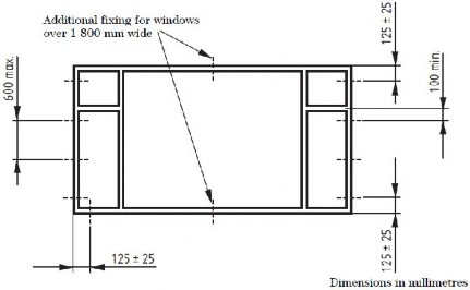
Wherever practicable all four sides of the frame should be secured as follows. a) Corner jamb fixings should be between 100 mm and 150 mm from the external corner. b) No fixings should be less than 100 mm from the centre line of a mullion or transom. c) Intermediate fixings should be at centres no greater than 600 mm. d) There should be a minimum of two fixings on each jamb. e) On windows and doorsets over 1 800 mm wide, central head and sub-sill fixings should be provided.
Coupled assemblies Coupled assemblies are usually delivered to site as separate units, to ease handling and minimize damage. When building up components into the required assembly, care should be taken to keep coupling joints equal, and frames both aligned and plumb. When coupling joints are also to be used as expansion joints, they should have seals, such as bedding mastic, expanding bituminized tapes, or flexible polymer gaskets, placed within the joint during the assembly operation. It is not sufficient to rely solely on external pointing sealant. Coupled assemblies should be fastened together in accordance with the manufacturer’s instructions. Where the coupling is structural, the system supplier’s recommendations should be followed.
Windows and doorsets should be installed plumb and square within the aperture, without twist, racking or distortion of any member in accordance with the manufacturer’s recommended tolerances, to operate correctly after installation and in accordance with the surveyor’s instructions.
Replacement windows and doorsets should generally be positioned to minimize the amount of making good, taking into account the following points.
- The new frame should bridge the DPM. Any damaged DPM should be repaired.
- The frame should be set as far back in the reveal as is feasible for better weather performance.
- The correct movement gap should be provided.
New Build the position of the window or doorset within the reveal is normally agreed at the time of original design and the installation should be in accordance with the agreed design. Open cavities discovered between inner and outer skins of brick or blockwork should be bridged or closed with an insulating material. Care should be taken to maintain the integrity of the DPM, and adequate purchase for fixing screws should be ensured, if need be with extended fixing lugs.
Installation packers Installation packers should be used adjacent to fixing positions to prevent outer frame distortion during installation. Installation packers should be resistant to compression, rot and corrosion. They should span the full depth of the outer frame. The fixings should be tightened so that the frame is held securely against the packers. Over-
Finishing
tightening can lead to distortion and should be avoided. Some lugs need to be packed off the substrate to prevent distortion. Where enhanced security is required, additional packers might be necessary adjacent to hinge and locking points. Debris or contaminants should be removed and any drainage paths should be cleared. Internal reveals should be made good as agreed, ready for the purchaser to redecorate if necessary. Any materials such as trims or sealant should not be applied on top of loose material. Protective tapes should be removed as soon as practicable, as ageing of tapes can cause difficulties in removal. Refer to the manufacturer’s guidance. Sand and cement should not be used to fill the gap between the outer frame and the substrate except for backfill for steel windows, nowadays usually limited to windows in stone surrounds or interior fair-faced brick and concrete. Where the replacement product has a smaller front to back dimension than the original, then there might be a mastic and/or paint line visible on the substrate which should be removed as much as practicable or covered with a trim. The method of, and responsibility for, repair to any render should be as agreed with the purchaser.
Installation – Fixing
There are two principal methods of fixing available, which may be used separately or in combination: through frame fixings and lug fixings. The surveyor is responsible for specifying the nature, location and quantity of the fixings, taking into account the manufacturer’s instructions. It is the responsibility of the installation company to ensure suitability, whether by recourse to third-party assessment or by some other means.
For correct fixing, each frame member should be fixed to the substrate or to an adjacent window or doorset to resist all likely imposed loads that could cause the frame to deflect.
- wind loads.
- operating loads.
- gravity.
- accidental impact.
- attempted burglary.
Fixing methods are affected by:
- the presence or absence of a wall cavity.
- the nature and condition of any cavity.
- the relative position of the frame and cavity.
- the position of the plaster line and the need to minimize disturbance and damage to interior decorations.
- The design of the reveal.
- Any requirements for fire resistance.
Wherever practicable the sides of the frame should be secured in accordance with the recommendations. If it is impossible to follow these recommendations, then, on large contracts, alternative positions should be agreed with the purchaser, and on domestic installations, the closest possible fixing positions should be used.
The presence of pre-cast concrete or steel lintels can make it impracticable or pose severe difficulties in achieving the recommended fixing distances. In these instances the use of polyurethane foam has proved a useful adjunct to mechanical fixings, but foam fixings should under no circumstances be used as the sole method of fixing the entire frame into the reveal.
A twist in such as ACVL130 lug anchor can provide can be installed into the outerframe then the lug connected to the sub structure. Screws should be sized to penetrate at least 25 mm into timber, plugged holes in brick, block, or masonry, unless equivalent demonstrable provision can be made by other means, e.g. in accordance with an appropriate structural code. Connections to steelwork up to 2 mm thick such as folded sheet lintels should be made with appropriate thread cutting screws. Connections to steelwork over 2 mm thick should be either into pre-tapped holes with machine screws of minimum 5 mm diameter, or with power-driven hardened self-drilling screws. Other proprietary mechanical fixing methods are available but will not necessarily be suitable for a given application. Fixings should be at least as corrosion-resistant as BS EN 1670:1998, Grade.
Installation – Glazing
Windows and doorsets can be delivered ready glazed, alternatively they can be supplied with glass units and pre-formed glazing gaskets to be applied on site in accordance with the manufacturer’s instructions. Some, systems in particular evolution, require glazing tapes. In all cases the manufacturer’s instructions should be followed. All glazing should conform to the recommendations given in the relevant part of BS 6262. In addition, any glass or insulating glass unit manufacturer’s instructions should be followed.
Inspection Installation
Setting Blocks Insulating/Safety Glass
All insulating glass units should be examined for damage prior to installation. Defective units should not be used.
Insulating glass units, setting and location blocks, distance pieces, frame to glass and bead to glass gaskets, bead to frame airseals, corner sealing blocks, beads and bead end caps, bedding and capping sealants should be installed in accordance with BS 8000-7
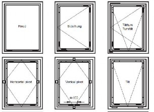
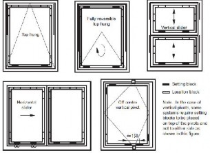
Figure 5 shows the setting and location block positions recommended in BS 6262. Insulating glass units incorporating safety glass should be oriented with the safety glass on the appropriate side. It is a legal requirement that the marking on the safety glass remains visible after installation. Insulating glass units with low emissivity coatings should be oriented in accordance with the manufacturer’s instructions. Failure to do so can render the coating less effective.
Installation – Sealing
The purpose of perimeter sealants is to repel water and prevent air leakage in the face of diXerential movement between the aperture and the window or doorset. Suitable sealants exhibit and retain flexibility and adhesion over this period. The movement class for the sealant will depend on the substrate material, the frame material and the dimensions of the joint between the frame and the opening.
Sealant Type Sealants should be tested and classified in accordance with BS EN ISO 11600. Unless an unusual and specific known requirement determines otherwise, they should be of low modulus and high elasticity, with movement capability of at least 20%. These characteristics should be identified on their packaging as class 20LM or 25LM.
Considerations
Perimeter joints should be sealed, with a sealant appropriate to:
- the frame surface.
- the substrate material.
- joint size and configuration.
- anticipated joint movement.
- anticipated exposure to weather.
It is essential that sealants are compatible with the frame material and the substrate. The presence of old oil-based mastics and bituminous DPMs can adversely affect the behaviour or appearance of otherwise correctly specified and applied sealants, through the migration of hydrocarbons to the surface of the new sealants.
Consequent photo-oxidation of the migrant products can aXect sealant performance and produce discoloration. This risk should be avoided by removal of unwanted mastic and by keeping sealant away from DPMs. In situations where sealants rely upon atmospheric moisture to initiate curing, deep filling should be avoided.
Sealant Backing
The sealant should be applied against a firm backing so that it is forced against the sides of the joint during application. To avoid failure in service, the sealant should not adhere to the backing because this would restrict the lateral movement of the joint. These recommendations can be achieved through the use of a closed-cell, oversize circular foam strip. For aluminium framed windows and doorsets, recommended best practice is to have an insulating fill inserted or injected wherever practicable around their full perimeter behind the external seal between frame and structural opening.
Drainage path — do not block.
Sealant.
Inau lotion when required.
Steel lintel.
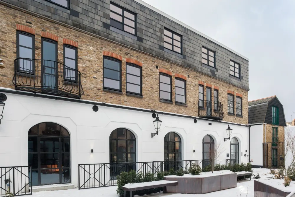
Commercial Aluminium Windows:
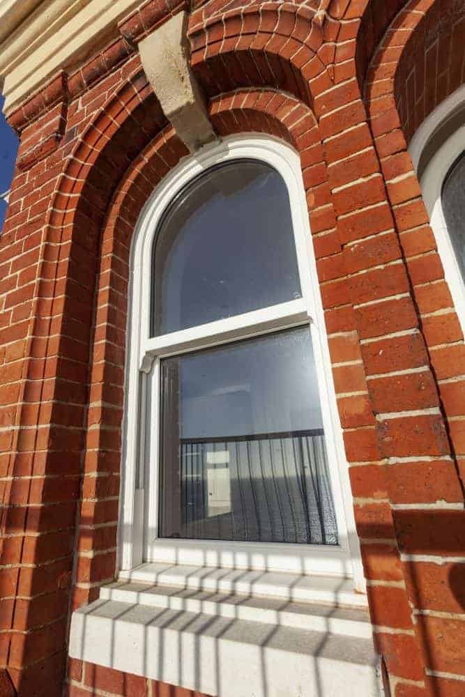
Illuminating Spaces with Elegance
In the realm of commercial glazing, windows serve as the eyes of a building, allowing natural light to flood interiors and connecting occupants with the external environment. Commercial aluminium windows offer a perfect combination of elegance, functionality, and durability, enriching the architectural aesthetic while enhancing the indoor environment.
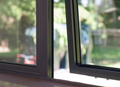
Aluminium windows are available in a variety of styles, including casement, sliding, tilt and turn, and pivot options, providing architects and developers with the flexibility to meet diverse design requirements and spatial constraints. With slim sightlines and sleek profiles, aluminium windows can help to , maximise views and enhancing the overall visual appeal of commercial buildings.
Beyond aesthetics, commercial aluminium windows prioritise energy efficiency and thermal performance, featuring advanced glazing options and thermal breaks that minimise heat loss and reduce energy consumption. This not only creates a more comfortable indoor environment for occupants but also contributes to the overall sustainability of the building.
Moreover, aluminium windows are inherently durable and low-maintenance, with robust construction that withstands the rigors of commercial use and exposure to the elements. This ensures long-term performance and reliability, reducing the need for frequent repairs and replacements and lowering lifecycle costs for building owners.
Furthermore, aluminium windows can be customised with a range of finishes, hardware options and glazing configurations to suit the unique design preferences and functional requirements of each project. Whether it’s a sleek office tower, a vibrant retail space, or a contemporary hospitality venue, aluminium windows offer architects and developers endless possibilities to create spaces that inspire, engage and endure.
When it comes to today’s modern architecture, UK aluminium commercial glazing stands out as a shining example of innovation, versatility and sustainability. From iconic skyscrapers to bustling retail hubs, aluminium glazing systems have reshaped the urban landscape, creating vibrant spaces that inspire, captivate and last.
As architects continue to push the boundaries of design and construction, aluminium glazing remains at the forefront, offering endless possibilities for creativity, functionality, and longevity. With its blend of aesthetic appeal, energy efficiency, structural integrity, and the elegance of commercial aluminium windows, aluminium commercial glazing is not just a building material—it’s a testament to the brilliance of contemporary architectural innovation.
 cone or mortar bed.
Trims and pressings
All trims should be compatible with the material of the frame and should be colour matched where specified. Finishing trims, where used externally, should be good exterior quality materials used in accordance with the manufacturer’s instructions. Cellular extruded PVC-UE trims should conform to BS 7619.
DPM.
Head arrangement and Sub-sill arrangement
Sesls nt.
DPM.
cone or mortar bed.
Trims and pressings
All trims should be compatible with the material of the frame and should be colour matched where specified. Finishing trims, where used externally, should be good exterior quality materials used in accordance with the manufacturer’s instructions. Cellular extruded PVC-UE trims should conform to BS 7619.
DPM.
Head arrangement and Sub-sill arrangement
Sesls nt.
DPM.
 Inau lot:ion wh en required. Sealant.

DPM.

Flush reveal frame bridging DPM joint width less than 6 mm
Insulation whoro roquirod.

Flush reveal with external render for replacement windows/doorsets with frame shuffled into position
Insulation where required.

Frame forward of DPM
1nsu lotion where req ui red.
Flush reveal frame bridging DPM joint width from 6 mm to 15 mm
In aul atio n wh ere required. Packing Piece.
Flush reveal with external render for replacement frames


5


6


7
8
Installation – Commissioning
Final Insepection After installation a final inspection should be carried out, preferably accompanied by the purchaser, to ensure that the installation is fully in accordance with the surveyor’s and manufacturer’s instructions. An example of a final checklist is given in Annex A.
Correct Operation It is essential that the purchaser is made aware of the method(s) of operation, locking and unlocking and fire egress. This should be accompanied by written operating and maintenance instructions such as those published by trade federations. Ideally, all occupants of a household, other than small children, should carry out the operation of the windows and doorsets, particularly the operation of safety restrictors and their release for egress, in order to identify any difficulties any occupant might have and to agree remedies. Where it is not possible to pass the instructions directly to the occupant, e.g. in the case of housing association refurbishment, then it is the responsibility of the purchaser to ensure that the instructions are passed on. Information on the ordering of spare keys should be provided. In addition, it is good practice to have the purchaser or purchaser’s designated representative sign off the installation after the inspection has been passed.
TECHNICAL INFORMATION
|
CLEANING, MAINTENANCE AND REPAIR PROCEDURE FOR ORGANIC PAINT COATINGS (ACRYLIC AND POLYESTER) ON ALUMINIUM AND PVC-U WINDOWS, DOORS AND ARCHITECTURAL PRODUCTS |
|||
|
|
INDEX |
|
|
|
CLEANING AND MAINTENANCE |
|
||
|
ALUMINIUM |
4 |
||
|
PVC-U |
5 |
||
|
REPAIR |
|
||
|
ALUMINIUM |
|
||
|
PVC-U |
6 |
||
|
FABRICATION AND INSTALLATION |
6 |
||
|
ORGANIC COATED ALUMINIUM |
7 |
||
|
REPLACING DAMAGED COMPONENTS |
8 |
||
|
WINDOW HARDWARE MAINTENANCE |
8 |
||
|
DOOR HARDWARE MAINTENANCE |
8 |
||
|
DATE 12/08/08 |
CLEANING, MAINTENANCE AND REPAIR |
PAGE 2 |
|
TECHNICAL INFORMATION
|
CLEANING, MAINTENANCE AND REPAIR PROCEDURE FOR ORGANIC PAINT COATINGS (ACRYLIC AND POLYESTER) ON ALUMINIUM AND PVC-U WINDOWS, DOORS AND ARCHITECTURAL PRODUCTS |
||
|
In compiling these guidelines we would also draw your attention to a publication by the Council for Aluminium in Building, 191 Cirencester Road, Charlton Kings, Cheltenham, Gloucestershire, GL53 8DF (Tel No: 01242 578278). “Guidance in the handling, care, protection, fixing and maintenance of aluminium windows and doors.” |
||
|
DATE 12/08/08 |
CLEANING, MAINTENANCE AND REPAIR |
PAGE 3 |
TECHNICAL INFORMATION
|
CLEANING, MAINTENANCE AND REPAIR PROCEDURE FOR ORGANIC PAINT COATINGS (ACRYLIC AND POLYESTER) ON ALUMINIUM AND PVC-U WINDOWS, DOORS AND ARCHITECTURAL PRODUCTS |
||
Note: T-Cut or similar automotive paint restorer may be used provided it is not too abrasive! Care must be taken not to abrade sharp corners of section or aris of beads too heavily where the paint film is normally thinner, and it should be remembered that this operation should not be carried out too frequently. Polish with a soft cloth to restore gloss and colour uniformity. |
||
|
DATE 12/08/08 |
CLEANING, MAINTENANCE AND REPAIR |
PAGE 4 |
TECHNICAL INFORMATION
|
CLEANING, MAINTENANCE AND REPAIR PROCEDURE FOR ORGANIC PAINT COATINGS (ACRYLIC AND POLYESTER) ON ALUMINIUM AND PVC-U WINDOWS, DOORS AND ARCHITECTURAL PRODUCTS |
|||
|
d) For extra protection a wax polish can be applied once or twice a year again polishing with a soft cloth to restore glass. (PVC-U) PVC-U profile, whether white self finish or woodgrain laminated, requires minimal maintenance. Occasional cleaning with soap and warm water is all that is normally required. The laminated woodgrain effect finish is resistant to normal household agents, e.g. ammonia water, petrol, alcoholic drinks (<45% vol alcohol), non-abrasive cleaners and water. It is not resistant to organic solvents, paint thinners and removers which is also applicable to white self finish material.
|
|||
|
DATE 12/08/08 |
CLEANING, MAINTENANCE AND REPAIR |
PAGE
|
|
TECHNICAL INFORMATION
|
CLEANING, MAINTENANCE AND REPAIR PROCEDURE FOR ORGANIC PAINT COATINGS (ACRYLIC AND POLYESTER) ON ALUMINIUM AND PVC-U WINDOWS, DOORS AND ARCHITECTURAL PRODUCTS |
||
|
Note: Beware swarf on benches, end damage of assembled frames in transit or on site and the careless use of sharp ended screwdrivers or other tools for forcing ‘snap-fit’ beads into position! If the paint film is unavoidably damaged and bare aluminium revealed, the damage must be repaired immediately using procedure 2b.
|
||
|
DATE 12/08/08 |
CLEANING, MAINTENANCE AND REPAIR |
PAGE 7 |
TECHNICAL INFORMATION
|
CLEANING, MAINTENANCE AND REPAIR PROCEDURE FOR ORGANIC PAINT COATINGS (ACRYLIC AND POLYESTER) ON ALUMINIUM AND PVC-U WINDOWS, DOORS AND ARCHITECTURAL PRODUCTS |
||
Hinges and locking mechanisms should be lubricated periodically to minimize wear and to ensure smooth operations. |
||
|
DATE 12/08/08 |
CLEANING, MAINTENANCE AND REPAIR |
PAGE 8 |

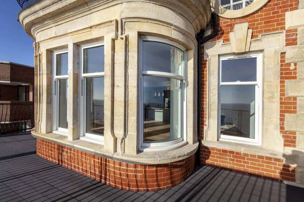
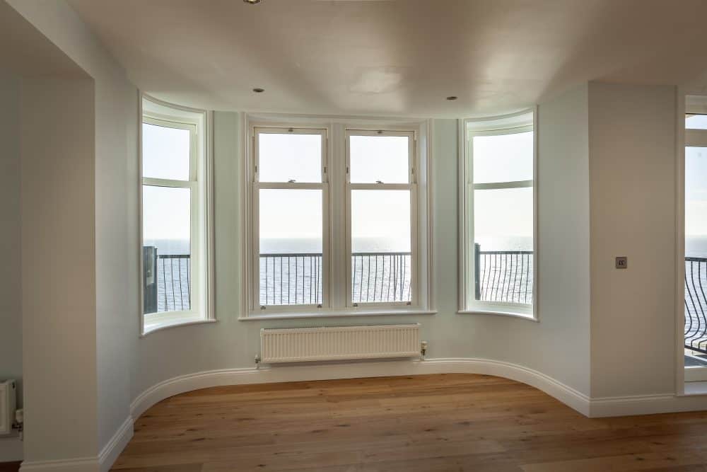
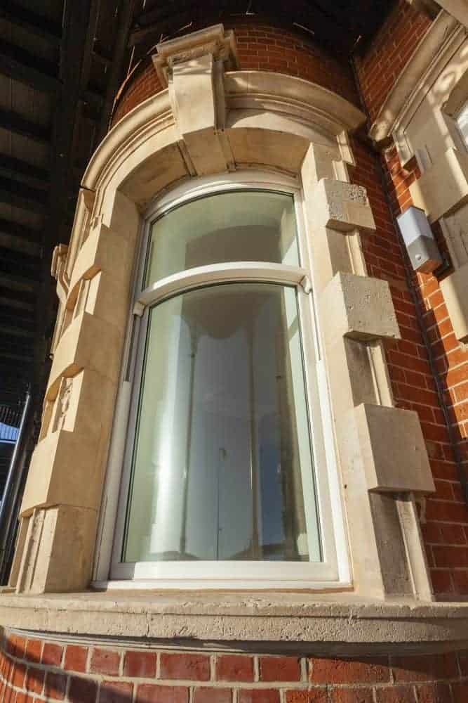
Cliff House, Felixstowe
VIEW PROJECT
Foxhill House, Chester
VIEW PROJECT
University of Sussex, Brighton
VIEW PROJECT
Varndean College, Brighton
VIEW PROJECTFrom sash windows to aluminium bifold doors, our high-quality products are engineered and manufactured right here in Britain. We work with fellow UK-operated companies, Spectus Window Systems, Smart Systems, and Jack Aluminium Systems, to deliver only the very best to our trade, commercial and residential customers.
How much do French doors cost to install in the UK?
The cost of installing French doors in the UK varies depending on the size, material, and design. At Mercury Glazing, we offer competitive pricing tailored to your specific needs. Please contact us for a personalised quote.
How to fit door handles?
Fitting door handles can be a straightforward process. First, measure and mark the position on the door, drill the necessary holes, then attach the handle with screws. For detailed instructions or professional fitting services, feel free to reach out to us.
How to replace patio doors?
Replacing patio doors involves removing the old doors, preparing the opening, and installing the new doors. It's a task best handled by professionals to ensure a perfect fit and functionality.
How much do patio doors cost?
The cost of patio doors varies based on size, material, and design. Contact us at Mercury Glazing for a bespoke quote that matches your specific requirements.
How much are French doors?
The price of French doors depends on the material, size, and design details. We offer a range of options to suit various budgets. Please get in touch for a tailored quote.
OUR ACCREDITATIONS